Simple Octal Keyboard using AT89C2051 microcontroller
Experiment Name: Simple Octal Keyboard
Objective of project: To learn how to program a microcontroller using assembly language for interfacing octal keyboard 0-7.
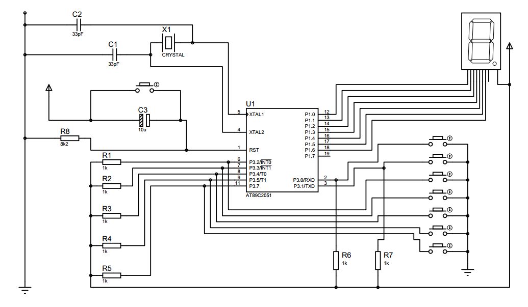
Circuit Diagram:
Objective of project: To learn how to program a microcontroller using assembly language for interfacing octal keyboard 0-7.
Circuit Diagram:
Components:
● AT89C51 Microcontroller
● Bread board
● 9V DC battery
● Common Anode 7 segment Display
● Resistors -8.2k
● Transistor BC547(NPN)
● 33pF Ceramic capacitors x 2
● 11.0592 MHz crystal
● 10μF Electrolytic capacitor
● Push switch
● UM66 musical IC
● Buzzer
● Jumpers
● Connecting wires
● Voltage regulator
Flowchart:
Code:
ORG 00H
MOV
DPTR, #CACODE
MOV
P3, #0FFH
MOV
P1, #7FH
;;all keys are open ?
KYCHK: MOV
A, P3
SETB
ACC.6
CJNE
A, #0FFH, KYCHK
CALL
DBONC ;20ms
CALL
DBONC
;; read key board
KYPUSH: MOV A, P3
SETB
ACC.6
CJNE
A, #0FFH, RDKEY
SJMP
KYPUSH
RDKEY: CALL DBONC
CALL
DBONC
CPL
A
MOV
R0, #00H
DETEKT: RRC
A
JC
KYCODE
INC
R0
SJMP
DETEKT
KYCODE: MOV
A, R0
MOVC
A, @A+DPTR
MOV
P1, A
SJMP
KYPUSH
DBONC: MOV
R7, #0FFH
WAIT: DJNZ R7,
WAIT
RET
CACODE: DB 40H, 79H, 24H, 30H, 19H, 12H, 78H, 02H ; 0-7
END
Brief description of program:
I. Firstly, load 0-7 digit codes of 7 segment display into data pointer
II. Configure p3 port as input and p1 as 7Fh
III. Move the value of P3 into accumulator and compare whether it is equal to 0FFh
- If YES, Read P3 again.
- If NO, Read P3 and go to step IV.
IV. Complement accumulator and initialize a counter R0
V. Repetitively right shift carry the accumulator and increment counter until carry is 1.
VI. When carry is 1, retrieve key pressed code from data pointer and show it to segment display.
See the project at https://youtu.be/7_CHX7aCmoc


Comments
Post a Comment