Posts

Showing posts from July, 2018

3x3 Matrix Keyboard using AT89C2051 microcontroller

Image
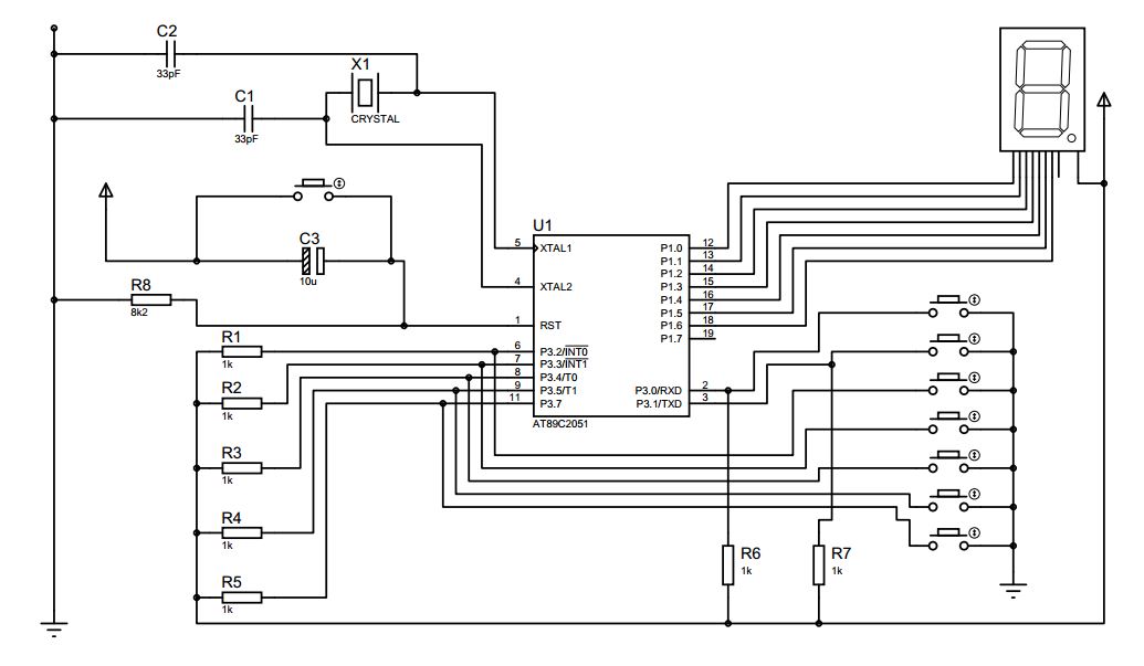
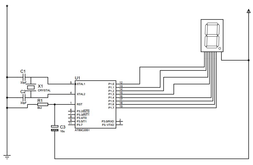
Project Name: 3x3 Matrix Keyboard Objective of Project: Showing 0 to 8 on a 7 segment display by using matrix theory connected to P3.0 to P3.5 Circuit Diagram: List of components: SL Name and Description Quantity 1 MCU 89C2051 1 2 7 segment display ( Common Anode ) 1 3 Resistance 1K Ohm 10 4 Capacitors 30pf (10 uf 50Volt(1), 100uf 50Volt(1)) 2 5 Crystal Q11.059A1 1 6 Voltage regulator 7805 1 7 Bread board 1 8 Connecting wires 9 Battery 9 Volt 1 10 Micro Push Type Switch 9 Flow Chart: Program: ORG 00h                 MOV P1, #0FFh                 Starter:                                 MOV P3, #00111000b                 MOV A, P3                 ANL A, #00111000b                 CJNE A, #00111000b, Starter               

Simple Octal Keyboard using AT89C2051 microcontroller

Image
Experiment Name: Simple Octal Keyboard Objective of project: To learn how to program a microcontroller using assembly language for interfacing octal keyboard 0-7. Circuit Diagram: Components: ● AT89C51 Microcontroller ● Bread  board ● 9V DC battery ● Common Anode 7 segment Display ● Resistors -8.2k ● Transistor BC547(NPN) ● 33pF Ceramic capacitors x 2  ● 11.0592 MHz crystal ● 10μF Electrolytic capacitor ● Push switch ● UM66 musical IC ● Buzzer ● Jumpers ● Connecting wires ● Voltage regulator Flowchart: Code: ORG 00H                                 MOV DPTR, #CACODE                                 MOV P3, #0FFH                                 MOV P1, #7FH ;;all keys are open ? KYCHK:                 MOV A, P3                                 SETB ACC.6                                 CJNE A, #0FFH, KYCHK                                 CALL DBONC       ;20ms                     

Door entry audio alarm with door number display on a 7 segment display.

Image
Experiment Name: Door entry audio alarm with door number display on a 7 segment display. Objective of project : To learn how to program a microcontroller using assembly language for door entry audio alarm and door number in a seven segment display. Circuit Diagram: Components: ● AT89C51 Microcontroller ● Bread  board ● 9V DC battery ● Common Anode 7 segment Display ● Resistors -8.2k ● Transistor BC547(NPN) ● 33pF Ceramic capacitors x 2  ● 11.0592 MHz crystal ● 10μF Electrolytic capacitor ● Push switch ● UM66 musical IC ● Buzzer ● Jumpers ● Connecting wires ● Voltage regulator Flowchart of program: Code: Brief description of program:  I. Firstly, load 0-7 digit codes of 7 segment display into data pointer II. Configure p3 port as input and p1 as 7Fh III. Move the value of P3 into accumulator and compare whether it is equal to 0FFh a. If not equal then go to open b. Else repeat III. IV.

Blink single LED among all LEDs connected to lines of port 1 to create running lights effect

Image
Project Name: Blink single LED among all LEDs connected to lines of port 1 to create running lights effect. Objective of Project: To blink single LED among all LEDs connected to all lines of port 1 to create running lights effect. Here port 1 is indicated by p1. If we work with port p1, then every bits of the port p1 will work together. So, we will be able to create running lights effect. Circuit Diagram: List of components: SL Name and Description Quantity 1 MCU 89C2051 1 2 LED 9 3 Resistance 1K Ohm 10 4 Capacitors 30pf (10 uf 50Volt(1), 100uf 50Volt(1)) 2 5 Crystal Q11.059A1 1 6 Voltage regulator 7805 1 7 Bread board 1 8 Connecting wires 9 Battery 9 Volt 1 Flowchart of program:

Show a letter on a single Common Anode 7 segment display.

Image
Project Name:  Show a letter on a single Common Anode 7 segment display. Objective of Project: Creating a program to show the small letter ‘t’ on a single Common Anode 7 segment display. Circuit Diagram: List of components: SL Name and Description Quantity 1 MCU 89C2051 1 2 7 segment display ( Common Anode ) 1 3 Resistance 1K Ohm 10 4 Capacitors 30pf (10 uf 50Volt(1), 100uf 50Volt(1)) 2 5 Crystal Q11.059A1 1 6 Voltage regulator 7805 1 7 Bread board 1 8 Connecting wires 9 Battery 9 Volt 1 Flowchart of program: Printout of Program: Brief Description of Program:   Here in this experiment, we used common anode 7 segment display to show the letter ‘t’. Let’s see how it